Tutorial
SVGs, gears and Tinkercad
What is it?
The Import function allows you to bring in both 2D and 3D images. Tinkercad Import supports SVG files.SVG is a language for describing two-dimensional vector graphics in XML. SVG stands for Scalable Vector Graphics and it is used to define vector-based graphics in XML format. Since SVG are XML files, SVG images can be created with any text editor, but it is often more convenient to create SVG images with a drawing program, like Inkscape.
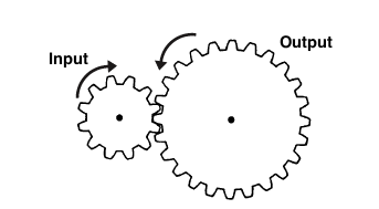
You use gears to slow down a motor and give it more strength. Torque is rotating strength. If the input gear is smaller, your larger gear will move slower, but the torque will be stronger.
As the speed increases, the strength of the torque decreases (large input).
As speed decreases, strength increases (small input).
You also use gears when your mechanism that is controlled by a motor is separated from the motor by geometry. The gears allow you to transfer the rotation of the motor across this geometry. When designing, you will often work from mechanism back to motor.
You could use gears with the same number of teeth to move the rotation. These gears are also going in opposite directions—you could create a claw.
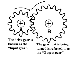
Gears also alter the direction of rotation. In the above example gear wheel A is rotating clockwise, but as it turns, gear wheel B is moved anti-clockwise.
If you know any two things about a gears—outer diameter and number of teeth—you can use some simple equations to find everything else you need to know, including the correct center distance between them.
- Number of Teeth (N)
- How many teeth are there in the gear
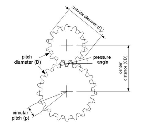
- Pitch Diameter (D):
- The circle on which two gears effectively mesh, about halfway through the tooth. The pitch diameters of two gears will be tangent when the centers are spaced correctly.
- Diametral Pitch (P):
- The number of teeth per inch of the circumference of the pitch diameter. Think of it as the density of teeth—the higher the number, the smaller and more closely spaced the teeth on a gear. Common diametral pitches for hobby-size projects are 24, 32, and 48. The diametral pitch of all meshing gears must be the same.
- Circular Pitch (p) = pi / P:
- The length of the arc between the center of one tooth and the center of a tooth next to it. This is just pi (ï€ = 3.14) divided by the diametral pitch (P). Although rarely used to identify off the shelf gears, you may need this parameter when modeling gears in 2D and 3D software like we're doing here. As with diametral pitch, the circular pitch of all meshing gears must be the same.
- Outside Diameter (Do):
- The biggest circle that touches the edges of the gear teeth. You can measure this using a caliper like Sparkfun.com's # TOL-00067.
Note: Gears with an even number of teeth are easiest to measure, since each tooth has another tooth directly across the gear. On a gear with an odd number of teeth, if you draw a line from the center of one tooth straight through the center across the gear, the line will fall between two teeth. So, just be careful using outside diameter in your calculations if you estimated it from a gear with an odd number of teeth. - Center Distance (C):
- Half the pitch diameter of the first gear plus half the pitch diameter of the second gear will equal the correct center distance. This spacing is critical for creating smooth running gears.
- Pressure Angle:
- The angle between the line of action (how the contact point between gear teeth travels as they rotate) and the line tangent to the pitch circle. Standard pressure angles are, for some reason, 14.5&Acir;° and 20°. A pressure angle of 20° is better for small gears, but it doesn't make much difference. It's not important to understand this parameter, just to know that the pressure angle of all meshing gears must be the same.
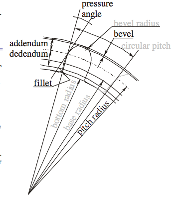
- Addendum:
- how much the tooth protudes beyond the pitch radius
- Dedendum:
- how deep goes the tooth before any fillet take place
- Pressure angle:
- The angle between the radial direction and the tangent to the tooth at the pitch circle. 20 is a good value.
Some Rules
The value of the base circle is based on pressure angle.- The smaller the pressure angle, the smaller the base radius
- The addendum must be less than the dedendum
- The dedendum must be more than the difference between the pitch and the base radius.
All of these gear parameters relate to each other with simple equations.
| To Get | You Have | Equation |
|---|---|---|
| Diametrical Pitch(P) Number of teeth per unit length |
Circular Pitch(p)
Number of Teeth(N) & Pitch Diameter(D) Number of Teeth(N) & Outside Diameter (Do) |
P=π/p P=N/D P=(N+2)/Do(approx) |
| Circular Pitch(p) Length of the arc from one tooth to the next |
Diametrical Pitch (P) | p=π/P |
| Pitch Diameter(D) | Number of Teeth(N) & Diametrical Pitch(P)
Outside Diameter (Do) &Diametrical Pitch(P) |
D=N/P D=Do-2/P |
| Number of Teeth(N) | Diametrical Pitch(P) & Pitch Diameter(D) | N=P*D |
| Center Distance(CD) | Pitch Diameter(D)
Number of Teeth(N) & Diametrical Pitch(P) |
CD=(D1+D2)/2CD=(N1+N2)/2P |
Blender Mechanical Gears 0.0.2©2004 Stefano <S68> Selleri
 This
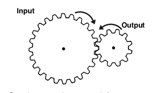
Stepping up produces a much faster output
speed, but mechanically delivers less power
This
Stepping up produces a much faster output
speed, but mechanically delivers less power
CALCULATING RATIOS
If the input gear (A) has 10 teeth and the output gear (B) 30 teeth, then the ratio is termed 3 to 1 and is written down as 3:1
Ratio = No. of teeth on the output gear B (30)>
        No. of teeth on the input gear A (10)
		= 3/1 and is written down as 3:1
Simply divide the amount of teeth from the output by the input gear to work out the ratio. In the above example, for every complete revolution of the input gear the output turns 1/3 of the way round. In other words it takes three turns of A to rotate B once. This means you are slowing down the action and is referred to in engineering terms as Stepping Down. If B were the input gear and A the output gear, then the opposite happens and we Step Up. Then with one turn of the input gear the output gear would turn three revolutions, giving a ratio of 1:3.
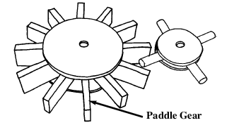
parallel gears work in a similar way to the In line ones but are much easier to construct. The larger one uses popsicle sticks instead of dowel and is referred to as a Paddle gear.
Designing
When designing and making gear wheels you need to apply a little common sense. For example, the load or pressure put on the gears in automata are usually very small compared to that of a car gear box. This allows you to get away with things that you couldn't in other machines. However, you still have to follow some simple engineering guidelines. You will need to identify what you want to get from the gears. Try running through this simple check list;- Do you want the gears to step up or
step down? (speed up or slow down
the performance).
- Do you want the gears to run
parallel, or at an angle of 90° to
change the direction of the drive?
- What size do you need to make
them? (small space means making
smaller gears and this can get tricky).
What's the tutorial?
- If you don't have Inkscape, download and install it from here. Otherwise open the application.
- Under the Extensions menu, select Render>Gear...
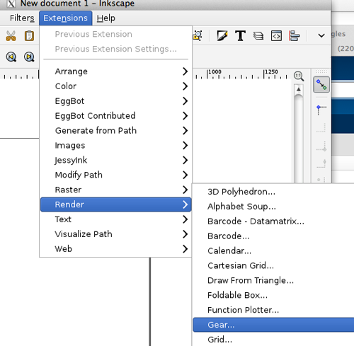
- Create a gear using the dialog box. Click Apply
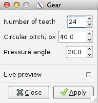
- When the gear is rendered, the dialog box does not disappear. Just click on Close.
- If you are on a Mac, you may run into this error message:I found installing the Eggbot extensions for Inkscape solved this issue.
The fantastic lxml wrapper for libxml2 is required by inkex.py
and therefore this extension. Please download and install the
latest version from http://cheeseshop.python.org/pypi/lxml/, or
install it through your package manager by a command like: sudo apt-get install python-lxml
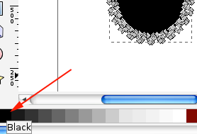
- Select Edit Path by Nodes (F2), click on the shape and fill it
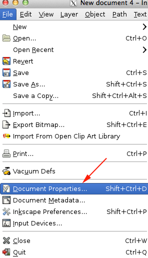
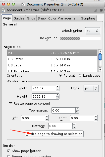
- From File menu select Document Properties or press SHIFT+CTRL+D
- Toggle open the Resize Page to Content option
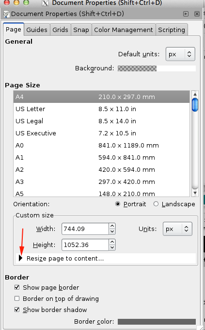
- Select Resize page to drawing or selection
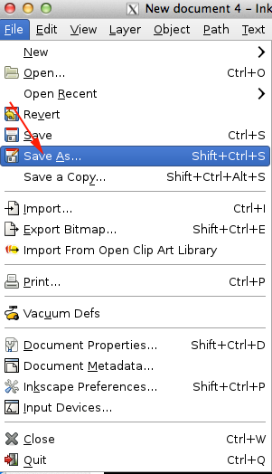
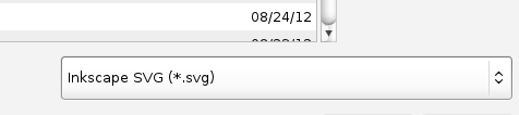
- Save the Drawing as an SVG
- Open a webGL enabled browser like Google Chrome or Firefox
- Navigate to tinkercad.com
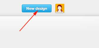
- Once you have signed in or created a new account, click the button to design a new thing:
- Instead of dragging a shape on to the work plane, toggle open the import menu
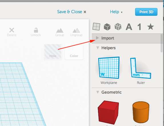
- Select File and then press Choose File
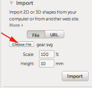
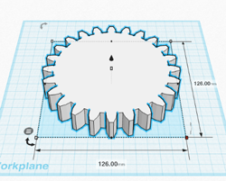
- Once you have chosen a file, press Import
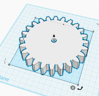
- Once imported, you can resize:
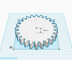
- Move a cylinder over, select the gear and the cylinder and use the Align Tool to align the shapes:
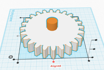
- Holding down OPTION/ALT+Shift, resize the cylinder as needed. Turn it into a hole, group the shapes
Now what?
- Upload your own 2D to 3D shapes to Thingiverse
- Come back tomorrow for more information and inspiration!
